This page is a part of the Computer Vision Wiki. The wiki is devoted to computer vision, especially low level computer vision, digital image analysis, and applications. The exposition is geared towards software developers, especially beginners. The wiki contains discussions, mathematics, algorithms, code snippets, source code, and compiled software. Everybody is welcome to contribute with this in mind - all links are no-follow.
Algorithm for Binary Images
From Computer Vision Wiki
Start with Binary Images.
In this article the algorithm for analysis of binary images is explained in detail and illustrated with C++ source code. MATLAB may be a better illustration tool, in general. However it does not support pointers which is a key here.
Contents |
The data structure
The input image of the algorithm is a binary 2D image, i.e., an array of 0s and 1s with dimensions dim1 and dim2.
bool image[ dim1*dim2 ];
The algorithm partitions the image by providing boundaries of the objects. Geometrically, these boundaries are circular sequences of directed edges of pixels in the image. In other words, these are 0- and 1-cycles. The first task is to count them.
long betti[2] = {0,0}; // Betti numbers = number of current cycles of each dimension
At each step we will update a Boolean array - the current frame.
bool *CurrFrame = new bool [ dim1*dim2 ];
As pixels are added, this array is incrementally changed - pixels are added - and analyzed by the algorithm. At every step, the cycles that have no descendants are called current cycles. Similarly, the edges that represent current cycles are called current edges. They are exactly the edges of objects visible in CurrFrame.
Cycles in the image are represented by nodes in the graph. In this graph, the cycles are related to each other to record the changes in the topology of the image in terms of merging and splitting of components and holes as the image develops. In particular, the 0- and 1-Betti numbers are updated at every step. The graph is implemented as a linked list. Each element of the list has pointers to the descendant(s) of the cycle. For the sake of image simplification and visualization, the list of current cycles has to be maintained at all times. Therefore, we have pointers to the next and previous current cycles on this list.
struct Cycle
{
struct Cycle *next[2]; // it may split
int Dim; // dimension
struct Cycle *linkF, *linkB ; // pointers to other current
                              // cycles on the list, forward and back
}
Thus, the data structure for the image is an acyclic binary directed graph. The regions and holes are represented as nodes of this graph. Each node representing a region or hole is connected to the nodes representing regions and holes that existed previously (its parents) or appear later (its children) by directed edges, or arrows, of the graph. The arrows (one or two from each node) indicate merging and splitting of the regions as we add vertices, edges, and pixels, Adding Pixels. There are no circular sequences of arrows. Each node of the graph contains a pair of links (pointers) to next nodes. If the cycle is merged with another, one link used, if it splits, two. This information is used even after the cycle ceases to be current, i.e., after a merge or a split.
We also connect each edge in the image to the cycle it created when the edge is added. This allows one to find the current cycle corresponding to a given edge. This is accomplished by following the pointer from the edge to its original node and then following the links of the graph to find the current node. This approach allows one to avoid reassigning these cycles to each edge of the new cycle (like relabeling of components) after every merge. In addition, only one of the two cycles emerging after a split has to be reassigning . This is implemented later.
The following command creates a node for the given edge.
struct Cycle *CreateCycle( int *edge )
{
struct Cycle *Cycle0 = new struct Cycle;
Cycle0->next[0] = NULL;  Cycle0->next[1] = NULL ; // no kids so far
Cycle0->Dim = 0;// to be determined
Cycle0->linkF = NULL Cycle0->linkB = NULL;// disconnected from the the list of current cycles so far
GiveCycle( edge, Cycle0 );// assign the edge to the cycle, below
AttachCurrCycle( Cycle0 );// add the cycle to the current list, below
return(Cycle0);
}
We maintain the list of current cycles by the commands below. The first one adds the node to the list by attaching it behind the last current cycle.
struct Cycle LastCurrCycle;
void AttachCurrCycle( struct Cycle *Cycle0 )
{
if( LastCurrCycle == NULL ) LastCurrCycle = Cycle0;
else
{ Cycle0->linkB = LastCurrCycle;
LastCurrCycle->linkF = Cycle0;
LastCurrCycle = Cycle0;
}
}
The second command removes the node of the given cycle from the list and updates the list. It is used when a cycles ceases to be current.
void DetachCurrCycle( struct Cycle *Cycle0 )
{
if( Cycle0 == LastCurrCycle ) LastCurrCycle = Cycle0->linkB;
if( Cycle0->linkF != NULL ) Cycle0->linkF->linkB = Cycle0->linkB;
if( Cycle0->linkB != NULL ) Cycle0->linkB->linkF = Cycle0->linkF;
Cycle0->linkF = NULL;
Cycle0->linkB = NULL;
}
A look-up list of all current edges is also maintained so that all current edges have pointers to corresponding cycles. Each edge is a 4-vector given by 2 integers representing the location of its initial point and 2 integers (from -1, 0, and 1) representing its direction.
EdgeToCycle = new struct Cycle *[ (dim1+1)*(dim2+1)*3*3 ];
There may be also a pointer from each node to one of the edges. This pointer provides a starting point for the boundary. This makes it possible to recover the cycle explicitly whenever necessary by following edges so that black pixels are to the left and white to the right of the edge. Thus, neither components nor their boundaries have to be explicitly recorded.
The run through pixels of the image
At every step of the run through the image, the value of the pixel in the image is considered. If the color is white, skip to the next step. If the color is black, execute AddCell. Every time a cell is added, the topology of the image changes, the graph, the list of current cycles, and the Betti numbers are updated.
for( k=0; k < dim1; k++ )// start the (k,l) pixel
for( l=0; l < dim2; l++ )
{
if( CurrFrame[ l+dim2*k ] == 0 )// if the new pixel is black..
   AddCell( k, l );
}
The AddCell command first adds one by one each of the 4 vertices of the pixel unless that vertex is already present as a part of another pixel. It has then a pointer to a cycle. AddVertex creates a node of the directed graph for each of these vertices. Next AddEdge adds one by one each of the 4 edges unless that edge is already present as a part of another pixel. It has then a pointer to a cycle. AddEdge either creates one node if this is a merge or two nodes if this is a split. The links for these nodes come from the SplitCycle and MergeCycles commands described below. The last step of AddCell is to add the pixel itself by removing the 1-cycle made of its 4 edges going counterclockwise.
void AddCell( int x1, int x2 )
{
int point[2];// adding vertices…
point[0]=x1;   point[1]=x2;   AddVertex( point ) ;
point[0]=x1+1; point[1]=x2;   AddVertex(point );
point[0]=x1+1; point[1]=x2+1; AddVertex( point ) ;
point[0]=x1;   point[1]=x2+1; AddVertex( point);
int edge[4]; // adding edges..
edge[0]=x1;   edge[1]=x2;   edge[2]=1;  edge[3]=0;  AddEdge( edge);
edge[0]=x1+1; edge[1]=x2;   edge[2]=0;  edge[3]=1;  AddEdge( edge );
edge[0]=x1+1; edge[1]=x2+1; edge[2]=-1; edge[3]=0;  AddEdge( edge );
edge[0]=x1;   edge[1]=x2+1; edge[2]=0;  edge[3]=-1; AddEdge( edge );
struct Cycle *Cycle0 = GetCycle( edge ); // removing the 1-cycle from the list of current cycles...
   DetachCurrCycle( Cycle0);
// marking the counterclockwise edges non-current
edge[0]=x1;   edge[1]=x2;   edge[2]=1;  edge[3]=0;  GiveCycle( edge, NULL );
edge[0]=x1+1; edge[1]=x2;   edge[2]=0;  edge[3]=1;  GiveCycle( edge, NULL );
edge[0]=x1+1; edge[1]=x2+1; edge[2]=-1; edge[3]=0;  GiveCycle( edge, NULL );
edge[0]=x1;   edge[1]=x2+1; edge[2]=0;  edge[3]=-1; GiveCycle( edge, NULL );
betti[1]--;
}
Creating a node means allocating memory for the data. By removing a node from the graph one may understand either its physical removal from the memory or simply marking it as non-current.
void AddVertex( int point[2] )
{ int edge[4];
edge[0] = point[0];
edge[1] = point[1];// location
edge[2] = 0;
edge[3] = 0;// no direction
struct Cycle *Cycle0 = CreateCycle( edge );
Cycle0->Dim = 0;
betti[0]++;
}
Unlike these two commands, the AddEdge command may changes the topology of the rest of the image. It is explained below.
Adding edges
Next, we describe under what circumstances MergeCycles and SplitCycle are executed. There are 3 cases.
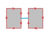
- a. If the edge being added connects two different 0-cycles, they are merged. MergeCycles with these two 0-cycles as the input creates a new 0-cycle. The 0-Betti number goes down by 1.
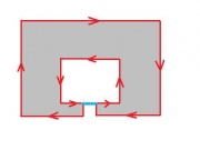
- b. If the edge being added connects a 0-cycle to itself, this cycle is split. SplitCycle with this cycle as the input creates a new 1-cycle and a new 0-cycle. The 1-Betti number goes up by 1.
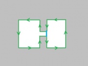
- c. If the edge being added connects a 1-cycle to itself, this cycle is split. SplitCycle with this cycle as the input creates two new 1-cycles. The 1-Betti number goes up by 1.
void AddEdge( int *edge )
{
// find the next edge
int forward[4]; StepForward( edge, forward, 0 );// below
// find the cycle corresponding to that new next edge
struct Cycle *CycleForward = GetCycle( forward );// below
// find the edge pointing the other way
int back[4]; Reverse( edge, back );
// find the next edge – in the opposite direction
int backward[4]; StepForward( back, backward,0 );// below
// find the cycle corresponding to that new next edge
struct Cycle *CycleBack  = GetCycle( backward );
int dim = CycleForward->Dim;
if ( CycleForward != CycleBack )
 MergeCycles( CycleForward, CycleBack, edge, back, 0 );
     // (a) 0 is the dimension of the new cycle
else
 SplitCycle( CycleForward, edge, back, 1 , dim );
    // (b) or (c) 1 and dim are the dimensions
    // of the new cycles
}
Exercise Implement the command Reverse (turning an edge in the opposite direction). Answer
To make the correct choice between MergeCycles and SplitCycle, there should be a quick way to identify the cycle corresponding to a given edge. This look-up procedure is called GetCycle. For this purpose, a look-up list is maintained. For each edge E, the list contains a pointer to the node that represents the cycle created when E was added (this pointer is NULL if the edge is not current). To make the algorithm fast, this list is only updated by SplitCycle. While traversing one of the created cycles it assigns to the edges the node corresponding to this cycle, next section.
For a given edge, GetCycle is carried out as follows. First step, use the look-up table to find the cycle node corresponding to the edge. Originally, it is the cycle created when this edge was added, later possibly reassigned by SplitCycle. Therefore, the cycle node may be non-current. Second step, starting from this node, follow the links of the directed graph as far as possible. The result is the current node and the current cycle corresponding to the edge. Because this is a binary graph, the search of the current cycle of a given edge is unambiguous. This is assured by following the two rules (1) in SplitCycle, reassign the edges of the first (next[0]) of the two cycles being created, (2) in GetCycle, follow the second link (next[1]) at each split.
struct Cycle *GetCycle( int *edge )
{
struct Cycle *temp;
temp = EdgeToCycle[edge[0]*(dim2+1)*3*3+edge[1]*3*3+(edge[2]+1)*3+(edge[3]+1)];
if( temp == NULL ) return(0);
while( temp->next[0] != NULL )  // if there are kids...
{
if( temp->next[1] != NULL )
  temp = temp->next[1]; // it’s a split
else
  temp = temp->next[0]; // it’s a merge
}
return( temp );
}
The following command assigns the given node to the given edge.
void GiveCycle( int *edge, struct Cycle *Cycle0 )
{
EdgeToCycle[edge[0]*(dim2+1)*3*3+edge[1]*3*3+(edge[2]+1)*3+(edge[3]+1)] = Cycle0;
}
Merging and splitting cycles
Next, we describe how MergeCycles and SplitCycle are executed.
Recall that for SplitCycle the numbers dim1, dim2 are the dimensions of the new cycles. As a result, a new cycle of dim1 or dim2 is gained.
void SplitCycle( struct Cycle *Cycle0, int *edge1, int *edge2, int dim1,  int dim2 )
{
struct Cycle *Son1 = CreateCycle( edge1 ) ;
struct Cycle *Son2 = CreateCycle( edge2 ) ;
TraverseCycle (edge1, Son1); // below
if ( Son1->Dim == dim1 )
 Son2->Dim = dim2;
else
 Son2->Dim = dim1;
Cycle0->next[0] = Son2;
Cycle0->next[1] = Son1;
DetachCurrCycle( Cycle0 ); // not current any more
if ( dim1 == 0 && dim2 == 0 )
 betti[0]++;
else
 betti[1]++;
}
Exercise Modify the above command to compute the perimeters of Son1 and Son2 based on the perimeter of Cycle0.
Exercise Same for the area.
Recall that for MergeCycles the number dim is the dimension of the new cycle. As a result, a cycle of dimension dim is lost.
void MergeCycles( struct Cycle *Cycle1, struct Cycle *Cycle2, int *edge1, int *edge2, int dim )
{
struct Cycle *Son = CreateCycle( edge1 );
Son->Dim = dim;
Cycle1->next[0] = Son;
Cycle2->next[0] = Son;
DetachCurrCycle( Cycle1 );// not current
DetachCurrCycle( Cycle2 );// not current
betti[dim]--;
}
Alternatively, the parental node(s) may be recycled.
Traversing cycles are only done during the SplitCycle command and only for the first of the two new cycles.
Exercise Modify the above command to compute the perimeter of Son based on the perimeters of Cycle1 and Cycle2.
Exercise Same for the area.
Traversing cycles
Traversing the cycle is accomplished by means of repeated application of the StepForward command below. From a given directed edge, StepForward moves to the next directed edge that must already be current. The next edge is found by checking which of the four possible next edges is current. This is verified by means of the look-up table and the GetCycle command. These edges are tested in this order from the end of the given edge, step left, step forward, step right, step backward (same edge directed backward). The command supplies the next edge of the cycle and also records whether it was left or right turn.

Exercise. Implement commands Plus (adding vectors), Turn (turning a vector left or right), Negative (turning a vector in the opposite direction).
void *StepForward( int *edge, int *temp, int *LR )  // ..from edge to temp edge
{ int black = 0; // 0 until we’ve found the next edge - temp
if( edge[3] == 0 && edge[2] == 0 ) // in case the edge is a vertex..
          black = 1; // do nothing
int d[2]; d[0] = edge[2]; d[1] = edge[3]; // original direction
if( temp != edge )
  {  temp[0] = edge[0]; temp[1] = edge[1]; // copy initial point
     temp[2] = edge[2]; temp[3] = edge[3]; // ...and direction
  }
temp = Plus(temp); // move forward – update the initial point
// next, find and update the direction
int i=0; // 4 possible directions
int lr=0; // 1 left turn, -1 right
while( black == 0 && i < 4 ) // 4 directions
{ temp[2] = d[0]; temp[3] = d[1]; // original direction of edge
// choosing the new direction...
switch( i )
{
case 0: Turn( temp, -1 )  lr = 1; break; // right turn
case 1:                   lr = 0; break; // straight
case 2: Turn( temp, 1 );  lr = -1; break; // left turn
case 3: Negative( temp ); lr = 0; break; // back
}
if (GetCycle(temp) != 0) // there is a current edge there..
         black = 1;      // then done
i++ ;
}
if ( black == 0 ) // no next edge – the edge is a vertex
{ temp[2]= 0; temp[3] = 0; lr = 0; }
if( LR != NULL ) *LR = lr; // the turn
}
As a result, one goes around the cycle until the initial edge is reached again. Traversing a cycle can also be carried out by simply maintaining a list of cycles as sequences of edges or vertices.
While traversing the cycle, the dimension of the cycle is determined by evaluating the total turn – if it is right (clockwise) the dimension is 0, otherwise it is 1. During the execution the cycle is assigned to all edges.
void TraverseCycle( int *edge, struct Cycle *Cycle0 )
{ int LR=0; // left-right turn
int Turn=0; // total turn (in the end it’s 4 or -4)
int temp[4]; // current edge
GiveCycle( edge, Cycle0 );
StepForward( edge, temp, &LR ); // first step
GiveCycle( temp, Cycle0 ) ;
while( edge[0]!=temp[0] || edge[1]!=temp[1] || // until the same edge..
edge[2]!=temp[2] || edge[3]!=temp[3] )
{
Turn+= LR; // total turn
StepForward( temp, temp, &LR ) ;
GiveCycle( temp, Cycle0 ) ;
}
if( Turn > 0 )
Cycle0->Dim = 1; // counterclockwise
else
Cycle0->Dim = 0; // clockwise
}
Exercise. Add to TraverseCycle the option of plotting cycles, with different colors for different cycles.
Exercise. Create a simple interface for the program with output only the Betti numbers of the image. Verify the correctness of the Betti numbers for some sample images.
Exercise. Use the list of current cycles to plot them, one by one.
Exercise. Even though only a part of a dark object is visible in the image, it is counted. Modify the algorithm so that 0-cycles that touch the border of the image are not counted.
Exercise. When only a part of a light object is visible in the image, it is not counted. Modify the algorithm so that 1-cycles that touch the border of the image are counted.
Exercise. Design the algorithm for hexagonal and triangular cells. Answer
Exercise. Design an algorithm for cells arranged in a circle as in a retina. Answer
Exercise Implement computation of the perimeter of a cycle. Add Cycle0->Perimeter to the structure.
Exercise. Implement computation of the area enclosed by a cycle. Add Cycle0->Area to the structure. Hint: use Green’s theorem [1].
Exercise. Design a character recognition system. Answer
Continue to Image Simplification.
Continue to Binary images - implementation.
Continue to Homology in 2D.
Digital discoveries
- Casinos Not On Gamstop
- Non Gamstop Casinos
- Casino Not On Gamstop
- Casino Not On Gamstop
- Non Gamstop Casinos UK
- Casino Sites Not On Gamstop
- Siti Non Aams
- Casino Online Non Aams
- Non Gamstop Casinos UK
- UK Casino Not On Gamstop
- Non Gamstop Casino UK
- UK Casinos Not On Gamstop
- UK Casino Not On Gamstop
- Non Gamstop Casino UK
- Non Gamstop Casinos
- Non Gamstop Casino Sites UK
- Best Non Gamstop Casinos
- Casino Sites Not On Gamstop
- Casino En Ligne Fiable
- UK Online Casinos Not On Gamstop
- Online Betting Sites UK
- Meilleur Site Casino En Ligne
- Migliori Casino Non Aams
- Best Non Gamstop Casino
- Crypto Casinos
- Casino En Ligne Belgique Liste
- Meilleur Site Casino En Ligne Belgique
- Bookmaker Non Aams
- カジノ ライブ
- онлайн казино с хорошей отдачей
- スマホ カジノ 稼ぐ
- ブック メーカー オッズ
- Top 3 Nhà Cái Uy Tín Nhất
- Trang Web Cá độ Bóng đá Của Việt Nam
- Casino En Ligne Avis
- Casino En Ligne France
- Casino En Ligne
- 꽁머니 토토
- Casino Online Non Aams
- Migliori Casino Non AAMS
- Meilleur Casino En Ligne
- Casino En Ligne France Légal
- Casino En Ligne France Légal
- Casinos En Ligne
- Mejores Casinos Online
